(Copyright by Pete Paraska. Donated to the Public Domain by Pete Paraska. Distribute to anyone interested but don't charge a thing. Please be very careful working with this circuit. The current is considerable and you could burn the harness and car up if not careful. I am not responsible for any damages from the use of the following information. Use at your own risk. If you see errors, please report them to me at pparaska at verizon.net)
The following is my modification of the Headlight wiring for 240Z's. I made this modification in order to take the current load off of the Headlight switch and put the load onto two relays, giving more current to the lights at the same time.
This circuit is intended to be installed by splicing it into the stock 240Z wiring harness on the right fenderwell. I used wire colors for the 73 240Z, although I believe they are the same for all years.
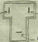
Find the following wires in the harness between the firewall and the connector in front of the radiator support that the right headlight sub-harness plugs into. The connector is T shaped with three male blades in it:
The wire on the left is Red with a Black stripe (RB). In the OE 240Z wiring, this wire is grounded when the low/high beam switch is in the low beam "position".
The wire on the right is Red with a White stripe (RW) (on the left headlight). Unfortunately, on the right headlight it is also Red with a Black stripe. From the high/low beam switch it is Red with a White Stripe. In the OE 240Z wiring, this wire is grounded when the low/high beam switch is in the high beam "position".
The wire on the bottom is Red with no stripe (R) on the Right headlight, and Red with Yellow stripe (RY) on the Left headlight. In the OE 240Z wiring, these wires go to the left and right headlight fuses.
The changes that are made are as follows:
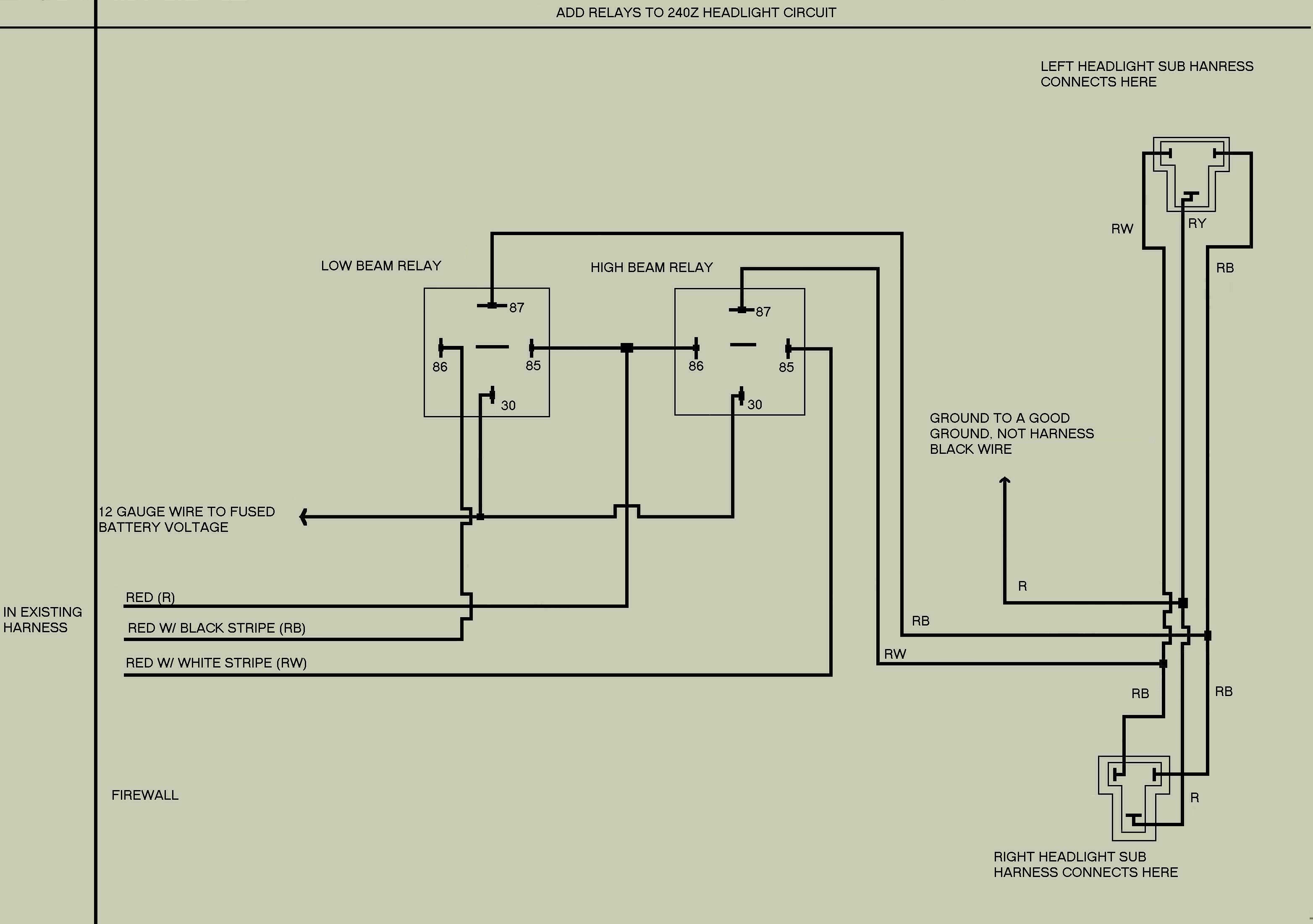
1) Find the CORRECT Red (R), Red with Black stripe (RB), and Red with White Stripe (RW) in the harness that runs along the right frame rail / inner fender. Cut each of these at a convenient place where you will mount the two relays (fender well or in front of radiator support).
2) From the firewall, the Red wire will run to the coils of both of the two 30 or 40 amp automotive relays that will be used. You can get these relays at Radioshack, etc. The sockets can be found at Digikey.com, or possibly at Radioshack. You can also cobble the relay box out of another car to get these sockets. It's advisable to use sockets and not wire to the relays themselves. The coil terminals on these relays are marked with the number "85" and "86" - there is no coil polarity, so the Red wire (R) can be hooked to either one of these on both relay sockets.
3) To the other relay coil terminals, the Red with Black (RB) and Red with White (RW) wires coming from the firewall should be connected, respectively. With the headlight switch on, the relay with the RB wire connected to the coil terminal (85 or 86) will be energized when the low/high beam switch is in the low beam "position". Likewise, with the headlight switch on, the relay with the RW wire connected to the coil terminal (85 or 86) will be energized when the low/high beam switch is in the high beam "position".
4) Run a good sized (12 gage) hot wire from the battery or alternator output with either a 16 gage fusible link or a good 40 amp maxi-fuse at the voltage source (battery or alternator output) to the "arm" (terminal 30) of both relays. IF you are running really high current bulbs, you may want to boost the wire size, fusible link or fuse. You should also put an inline fuse of 30 amps in this wire near the connection to the relay. This is the wire that will supply the high current to the headlights, and that 30 amp fuse is the new headlight fuse.
5) Run a good sized (10 or 12 gage again) ground wire to a solid ground. This will connect to the (R) and (RY) wires (tie them together) that go to the headlight sub-harness connectors. This is the new ground for the headlights.
6) Connect the (RB) wire from the headlight subharness side (the cut wire that goes out to the radiator support and to the headlight sub-harness connectors) to terminal 87 of the low beam relay.
7) Connect the (RW) wire from the headlight subharness side (the cut wire that goes out to the radiator support and to the headlight sub-harness connectors) to terminal 87 of the high beam relay.
You now have relays and short runs of wire to power the headlights. Only the OE right headlight fuse in the fuse panel is used (it powers the relay coils only). The left headlight fuse should be removed and the end of the (RY) wire coming from the firewall should be taped off. It is no longer needed.
Click here for a circuit diagram of this circuit. Many thanks to Dave Carr for taking my sloppy hand-drawn diagram and coming up with the nice version you see on the linked page.