A Photo Essay on the Construction of the Big Block Datsun
The
Beginning
We
will address the issues of “why a big block” and why a drag car vs. a road car
in other venues. The following is a
description of how the car was built, and how some design considerations
influenced the labor involved.
Occasional references are made to the “JTR method” of doing a
small-block swap.
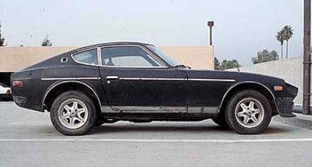
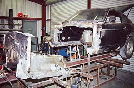
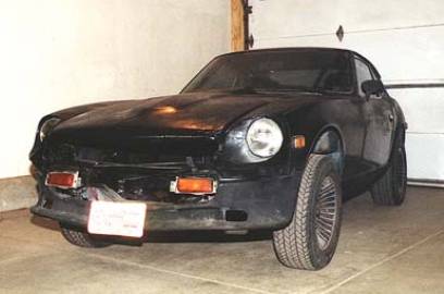
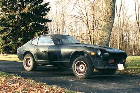
The car is a 1978 280Z, originally with an automatic
transmission. It was purchased in Las
Vegas in May 1999, for the princely sum of $600. Here’s how the car looked in its nearly stock form:
With the choice of big block as a given, several problems immediately cropped up. SBCs and BBCs have the same mounting pattern, so conceivably the JTR-type engine mounting strategy could be used. However, that would make the car severely nose-heavy and would place great stress on the steering crossmember. It would also be a tight fit. Since it only makes sense to build a stout BBC, the car has to be able to take the torque and put the power to the pavement. Even if a weak engine is installed temporarily, there has to be provision for future growth. That means significant structural reinforcement. But putting in a serious cage means stripping the interior to prepare for cutting and welding. So, it was decided to form a combined answer to the various design challenges and to undertake an engine setback involving significant surgery to the car’s unibody. The engine was set back by relocating the firewall aft by 6.25”.
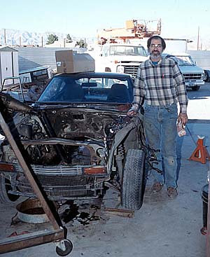
Firewall relocation can entail dealing with intricate compound curves in sheet metal. If the “after” does not match up with the “before”, gaps will remain, which would be difficult to fill. After some careful measurements, it was decided that a natural setback for the firewall was about 6”. This could be achieved by what on first blush may appear to be radical means: cutting off the front clip, then cutting out the firewall and floor as one unit, shortening the floor and gutting the sheet metal “box” where the windshield wiper motor used to reside, and welding the firewall/floor unit back in. It was decided that this would be cleaner and stronger than the alternative method of leaving the frame rails intact but cutting out the firewall around them. Frankly, I’m not convinced that this decision was wise – but it worked. I was not the guy doing the welding and cutting; this guy was:
The Surgery
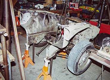
The car was built on a chassis jig. The two pictures below show what was essentially the starting state, after the car was stripped down to the shell, and a later stage in the construction of the car. The “before” (left) shot shows the way a stock Datsun looks, especially in terms of firewall location. The “after” (right) is with the firewall setback and welding of sheet metal patches to reconnect the frame rails and the front clip to the main unibody. Outboard of the inner frame rails, the before and after look strikingly similar. In the engine compartment, 6.25” inches of firewall setback can be seen.
Here is a shot of the front clip removed from the car.
The cutting was done pretty
much in one vertical plane, as if a huge guillotine lopped off the front
clip. Note the square vertical bars
running down from the frame rails. They
were used to locate the front clip for reinstallation, so that the suspension
alignment would be retained and the clip would not be welded in crooked.
And here’s a shot of the firewall and floor pan unit cut
out from the car:
The picture on the left below shows the firewall/floor unit temporarily reinstalled in its stock position. The firewall assembly will be slid back so that there’s some overlap between the ledges of the firewall and of the rest of the unibody, for a stronger joint. The picture on the right shows the resulting gap between the front clip and the newly set-back firewall assembly. This gap will have to be filled with sheet metal and with reinforcements for the severed frame rails.
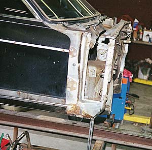
The Chevy 454 big block
engine, temporarily painted black, can be seen peering through the gap. The distributor is about 0.75” forward of
the firewall, much like the SBC distributor would be in the “JTR position”.
The Reconstruction
Taking advantage of the missing floor, the main portion of the roll cage was welded together outside the car. Then the cage was lifted into the car and eventually welded in several places to the unibody. For instance, the main roll hoop was welded to the “corners” at the front of the rear windows, thus turning the roll hoop into a kind of B-pillar. The idea was to maximize structural synergism between the roll cage and the unibody. In all-out race cars, the roof, rear panels and other sheet metal from the unibody is often non-structural. In the present case, we wanted to maintain the weather protection and overall integrity of the unibody as much as possible. So the unibody structure was retained where appropriate, and was used for example as a shear web to reinforce the roll cage tubes.
“Reassembly was the reverse of removal”. Well, sort-of. If Haynes were to have written the manual for such a project,
that’s probably what they would have said.
To reassemble the interior of the car, the floor was seam-welded back to the rocker panels. The transmission tunnel had to be modified to fit the externally-shifted Doug Nash 5-speed (shown below, with its mounting crossmember).
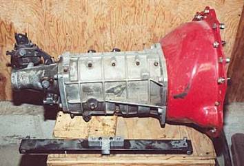
This transmission is not the best choice, as it has no overdrive and is very difficult to shift. However, it is incredibly strong, mates to a wide choice of bellhousings (a Lakewood blow-proof bellhousing was used), and has a deeper first gear (3.27:1) than the traditional 4-speeds, thus allowing for dragster-like launches with a streetable rear axle ratio – at least, in theory. The mostly-finished interior is shown below. One of the exhaust pipes is visible through a then-unpatched hole in the transmission tunnel. Also visible is the tubing that supports the driver’s seat, and the curved sheet metal that covers the transmission shifter.
As part of the firewall
relocation, the steering column assembly also had to be modified. The sheet metal box supporting the steering
column is now bolted to the dash bar (green arrow). The red arrow shows the seam where the floor was rejoined with
the aft sheet metal. Also visible are
the diagonals from the front strut towers, piercing the firewall and connecting
to the dash bar. The long tube in the
middle is the “backbone” tube that connects the front strut towers to the rear,
countering torsional and bending loads amongst all four wheels. Curiously, very few cars, short of GT-2 race
cars, have such a tube frame setup. In
the present case, the backbone tube is not particularly intrusive for the
driver’s comfort. But then again, this
is not exactly a commuter car!
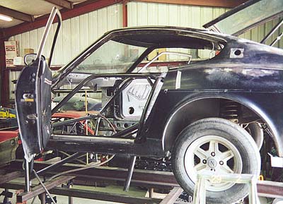
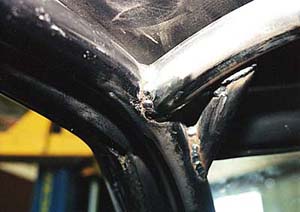
Here is a detail shot of one of the roll cage tube
connections and gussets. This is a
picture of the area near the top of the A-pillar on the driver’s side. Right above the cage members is the
still-intact headliner. It and the door
panels are the only remaining pieces of interior finishing materials! Here and elsewhere, the cage members were
installed as close as possible to the original sheet metal. Especially with this much firewall setback,
space inside a Datsun is tight!
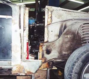
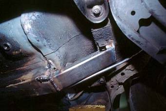
Because the roll cage is the main collection of structural elements, the frame rails were left comparatively alone. 280Z’s have much stronger frame rails than 240Z’s. After the firewall relocation and floor shortening, the stock frame rails terminated at the aft seam between the intact and the relocated sheet metal (red arrow in the above photo). From there, the frame rails were connected by rectangular steel sections to the subframe assembly of the stock rear clip. The most natural connection points were the stock rear sway bar mounts (see photo below). At present, the car has no rear sway bar – and there is the distinct possibility that it does not need one.
The
radiator of choice was a 29”-wide aluminum Griffin. To get it to fit, the stock sheet metal in the radiator area was
cut out, and the frame rails were notched.
The idea was that this part of the car’s structure is not important for
bearing loads. Also, with an eye to
future hood modifications for improved cooling and drag reduction, it was
important to reduce the vertical extent of the radiator assembly. So, the radiator was angled forward. That leaves a huge gap between the water
pump pulley and the radiator – which improves cooling and makes things easy to
work on. The assembly of under-hood
mechanical components can be seen in the following shot.
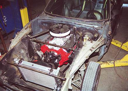
Note the diagonal braces from the front strut towers,
penetrating the firewall and collecting with a dash bar. From that connection point, the “backbone” tube
continues through the passenger compartment to another triangulated
assembly of tubes that connects to the rear strut towers and a load-bearing
beam (from the stock unibody) underneath the floor.
The radiator sits on transverse tubes which replace the
stock sheet metal assembly. Between the
front strut towers there’s a removable stress bar that is held by tabs welded
over the strut towers.
At this point it may be worth pondering as to why the entire
front clip was not dispensed with, replaced with tubes running from the cage to
the strut towers, forming a true tube frame. Then a double A-arm suspension could
be fitted, probably saving weight and improving suspension geometry. The answer,
in a nutshell, is cost and complexity. So many new variables would be introduced!
And this is, after all, a street car.
The tubing in the rear interior of the car is shown
here, prior to installation of the fuel cell and the firewall running across
the rear strut towers:
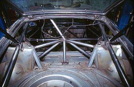
This forms the rear “node” of the tubing assembly. There are connections to the strut towers,
the aforementioned frame rail underneath the floor which anchors the front of the
rear suspension, and the main roll hoop.
From the roll cage main hoop, tubes connect to the rear strut towers and
continue to frame rails integrated with the unibody in the rear. These used to be the load-bearing members
for the huge crash bumpers in 280Z’s.
When this photo was taken the sheet metal “box” behind the seats was not
yet removed.
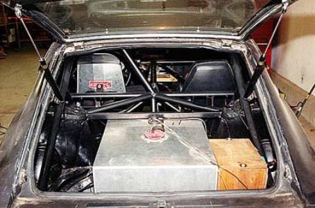
The present rendition of the same area can be seen in the
following view. The fuel cell is bolted
through the floor, as is the battery (currently in a wood box). A firewall between the rear strut towers
separates the fuel cell and battery from the passenger compartment. This will have to be continued with a full
cover over the fuel cell area, to meet NHRA requirements. The Kirkey aluminum driver’s seat, bolted to
the roll cage, is also visible. With
this installation, the fuel cell is mounted rather high, and significantly
upsets the interior room in the rear.
However, there are no issues of it getting heated up from the exhaust,
and the strong rear framing of the 280Z is left undisturbed.
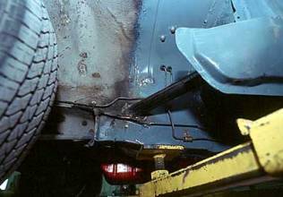
Here
is an “upskirt” picture of the car on a lift, taken with a 20-millimeter lens
(so the foreground/background are distorted).
Pointing
out features in going from the front of the car to the rear, some items of note
are: the tube supporting the radiator (marked with a blue arrow; at this stage
not yet connected to the front frame crossmember), the routing of the exhaust
past the bellhousing, diagonal supports from the footwells to the
tension/compression strut mounting area (red arrow), the transmission
crossmember (green arrow; it attaches to fittings welded to the frame rails),
and finally the mufflers. The oil sump
is completely behind the steering crossmember.
The crank pulley is immediately behind the steering rack.
The main purpose of the diagonal supports is to connect the roll cage to the frame rails in the front of the car, in a “triangulated” geometry. These are shown in the side view below. Also visible are the brake lines, rerouted to be outboard of the driver-side frame rail.
Also noticeable in this view, albeit somewhat distorted
by perspective, is that the oil sump hangs just slightly below the frame
rails. In fact, the lip of the
bellhousing extends to about the same depth, which is actually lower than the vertical
location of the lowest extremes of the exhaust tract.
The next two photos, also taken from underneath the car,
show the routing of the exhaust and other components around the engine
(passenger side and driver side) and the frame rails. In contrast to the JTR-type small block conversion, the starter
is completely behind the passenger-side tension/compression strut mount. Unfortunately it’s a very tight fit on the
passenger side between the starter and the exhaust – a problem which has not
been well resolved; the starter suffers from heat soak. And on the driver’s side, it is a tight fit
between the header collector flange and the tension/compression strut bushing.
Also visible are the motor
mounts, which protrude from reinforcing pads welded to the frame rails. The relocated fuel line is visible on the
left. With the motor mounted to the
frame rails, as opposed to the steering crossmember, a mechanical fuel pump can
be retained. The steering shaft (shown
by the pink arrow) actually pierces the driver’s side motor mount.
The motor mounts are shown in greater detail in
photographs taken from inside the engine compartment, with the engine removed
(passenger and driver side):
A slight notch in the
passenger-side frame rail (left, red arrow) is visible. This was necessary to accommodate the
exhaust headers (Hooker block-huggers).
The steering shaft passing through the driver-side motor mount can be
seen at right.
The Engine
The original plan for the engine was to first get a
junkyard motor that runs reliably but not necessarily well; then to replace
this with the GM Performance parts ZZ502.
The 502 fell off the radar screen when I learned that Gen VI stuff just
doesn’t have the aftermarket support of Mark IV stuff (for instance, just
getting a Gen VI aluminum flywheel was a challenge). I bought a forlorn-looking 454 from a metal scrap dealer (?) when
I lived in Los Angeles. The engine was
sitting in the back of his pickup truck – under a pile of other junk. It originated from a scrapped 1978 Suburban,
complete with the stupendously flowing 346236 truck heads.
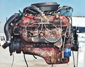
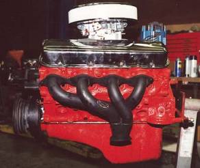
Unfortunately, after buying the engine I could not resist
the urge to hop it up. It received
headers, an aluminum intake, carb, and cam kit… with disastrous results. Here are the “before” and “after” pictures –
in the former, the engine was de-greased but otherwise unchanged; in the
latter, that’s how the engine looked when it went into the car. It’s amazing how merely cosmetic changes
have so much psychological effect. The
engine at left is a junk-yard refugee.
The one on the right looks like a hopped-up street terror – at least at
first.
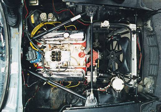
The following picture shows how things looked under the
hood, as of around December 2000. This
view shows just how far the engine is set back relative to what would have been
possible with the stock firewall location.
The valve covers are completely behind the front strut towers. The hood latch is gone, and is replaced by
two studs mounted to the strut tower diagonals, which engage clips riveted to
the top of the hood. The electric
cooling fan is a Flex-A-Lite 150. The
original coolant overflow can was recycled (it now sits where the charcoal
canister used to be).
So far, so good, right?
Well, not really. The car is
currently (January 2002) sitting engineless, while I figure out why the engine
bombed.
What went wrong?
Well, the engine never made the power that I would have expected from a
big block. Oil pressure was fine. Each cylinder made it to at least 130 psi on
a cranking compression test. But the
engine made guttoral knocking noises, even at idle but especially as rpms
increased, despite my best efforts to tune it.
It kept backfiring through the intake valves. Then pushrods started failing.
Finally it broke the #4 intake pushrod in half.
The Present
Condition of the Car
Here
are some pictures of the car in its current condition, at my house in
Ohio. I made a modification to the
headlight “sugar scoops” and the hood front lip, in an effort to reduce
drag. The result is cosmetically
questionable. The effect on the
aerodynamics remains to be seen.
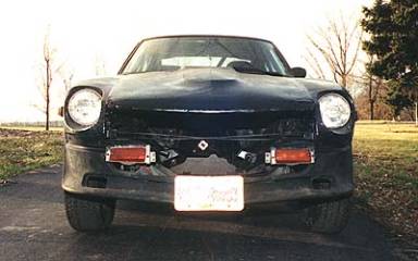
In this photo, the
differential flange is visible peering though the middle of the car (it’s
reflecting light off the flash); it’s a 3.7 R200 from a 1979 ZX. The front parking lights are in an unusual
position. Their mounting frames were
bent down about 120°,
as a prelude to later modifications that may involve covering up the headlight
scoops and installing rectangular headlights inboard of the fenders.
Here’s a ¾ shot showing how
high the car is “jacked up” with the engine removed. The springs are apparently stiffer than stock, courtesy of the
car’s previous owner. Wheels are
14”x7”.
These two shots of the
interior show the “backbone” tube (green arrow), main roll hoop (red arrow),
the gauge cluster (blue arrow) and the X-bars in the doorways (purple
arrow). The X-bars are welded in,
forming a part of the overall structure.
Not visible are the cage tubes running along the roof edges and just
forward of the door hinge lines, or the tubes connecting the main hoop to the
frame rails behind the seats. At the
front corners where the X-bars intersect the dash bar (top) and footwell
(bottom), reinforcing plates connect the cage to the unibody. Likewise for the legs of the main hoop, in
the area where the stock seat belt retractors used to fit. The cage is made of mild steel, with
critical members of 0.134” thickness.
My hope is that the structure of the car is “overbuilt” for now – and that it will be a healthy foundation as the engine comes together and evolves to higher power levels. It should easily be NHRA certifiable for a 9-second car – though I doubt that this car will ever run that fast on the drag strip.
At present, the car weighs just over 2700 lbs. That's with cast iron cylinder heads. With aluminum heads, aluminum water pump, mini-starter and lightened crankshaft, it should get down to 2600 lbs. Not exactly a lightweight amongst serious drag cars, but hopefully "light enough" for the street. I would rather have a light car with moderate power, than a heavy car with a lot of power - since the lighter car feels more sporty, even if it puts up the same performance numbers as the heavier one. Besides, lighter cars are easier to push!
Once the engine issues are sorted out, the next obstacle will either be traction or failure of some components in the rear end. At that point upgrades would start to make sense. In the meanwhile, I'm certainly open to suggestions on what to do with the engine. Calling all Chevy big block gurus! Are rectangular-port heads appropriate, even though this is a "street" car? To what power levels will the (stock) cast crank survive? Is it worth getting the crank internally balanced? Basically, I'm looking for a clean-slate solution.